Flexible Circuit Boards
The ability to select a flex PCB connector that matches up with design specifications and electronic elements is pivotal for optimizing the performance of a final electronic device. These connectors must seamlessly integrate with overall design layouts and accommodate varying electronic elements without sacrificing functionality or quality.
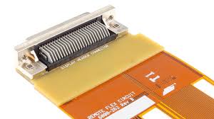
The types of connectors that are compatible with a flexible circuit board are many and varied. They can be used for a variety of purposes, ranging from providing a connection point to rigid circuit boards or another flex PCB to power and data transmission. The most common flex connectors include:
Depending on the specific application, some connectors may be more suited to a flexible circuit board than others. For example, if the device is designed to connect to other electronics, solderless terminals may be more appropriate. These are easy to terminate and do not require any heat to make contact with the conductors. Solderless terminals also offer a wide range of sizes and mounting options, making them suitable for any flex circuit design.
Types of Connectors That Are Compatible With Flexible Circuit Boards
On the other hand, if a flex circuit is being used to transfer data from one electronic component to another, power or data connectors are more suitable. These are specialized connectors that handle high-speed data transmission by sending light pulses across long distances. Some examples of these are USB, serial ports, and Ethernet connectors. Power connectors, on the other hand, supply electricity to a circuit board by transmitting power over short distances.
When selecting a flex connector for an electronic device, engineers and designers must also consider the amount of stress the connectors will be subjected to. This is because flex circuits are more susceptible to vibrations and extreme temperatures than rigid PCBs. The ability to tolerate harsh conditions is crucial for ensuring that data transmission is not disrupted.
Most flex and rigid-flex PCBs are made from polymer thick film construction, but some use traditional copper lamination techniques. This is ideal for applications that require a higher level of thermal stability and chemical resistance. The base layer for these circuits can be either FR4 or polyimide, and they are then laminated with layers of copper foil for conductors. The thickness of the copper foil can vary from extremely thin to standard thicknesses found in rigid PCBs.
While flex PCBs have many advantages over rigid ones, they require a different set of manufacturing processes and materials. A recent webinar hosted by Epec Engineered Technologies compared the number of steps that are required to manufacture a rigid PCB and a flex circuit board, with a rigid PCB taking 8 steps and a flex circuit board needing 17.
Due to their versatility, compatibility with various applications, and space allotment considerations, flex and rigid-flex circuits have become increasingly common. This is especially true for automotive electronics, where a desire to incorporate more and more technology into vehicles has led to the need for a thinner, more compact device. To meet this demand, a variety of new connectivity solutions have been developed to provide interconnect solutions that are smaller in centerline or pitch distances, have lower profile heights, and are lightweight.